ACCESSORY FITTING INSTRUCTIONS

JAGUAR

FITTING INSTRUCTION

WARNING
  • Accessories which are not correctly installed can be dangerous. Read the instructions carefully prior to installation. Comply with instructions at all times. If in doubt, contact your nearest approved retailer.
  • For all markets with the exception of Norway, vehicles with Vehicle Identification Number (VIN) between SADHB2R14K1F60001 and SADHD2S10K1F61604, a new VIN label showing the gross combination weight MUST be ordered and installed to comply with market legislation.
Specifications
Type Brink 5961
D-value 5.74 kN
Vertical coupling load 45 kg
Coupling class A50-X
Manufacturer Brink towing systems B.V.
Model application Jaguar X590
EC-type approval number towbar E11*55R01/06*11165*01
Maximum trailer weight 750 kg
CAUTION
  • Do not use the Jaguar Land Rover Approved Diagnostic Equipment to configure the detachable towbar electrics.
1
WARNING
  • For all markets with the exception of Norway, vehicles with Vehicle Identification Number (VIN) between SADHB2R14K1F60001 and SADHD2S10K1F61604, a new VIN label showing the gross combination weight MUST be ordered and installed to comply with market legislation.

For vehicles between Vehicle Identification Number (VIN) SADHB2R14K1F60001 and SADHD2S10K1F61604, install a new VIN label.

  1. Remove the current VIN label from the base of the B-pillar. Use a heat applicator to assist removal.
  2. Clean the area where the new VIN label will be installed.
  3. Remove the backing from the new VIN label and install the VIN label at the base of the B-pillar as illustrated.
2

Remove the loadspace cover from the vehicle.

3

Remove the loadspace treadplate.

For additional information, please refer to the official Workshop Manual. Loadspace Treadplate (501-05)

4

Release the lower rear edge of the loadspace left trim panel.

  1. Remove the 3 clips as illustrated.
  2. Remove the rear left side D-loop anchor point bolt.
  3. Remove the rear left side D-loop anchor point.
5
WARNING
  • This step requires the assistance of another person.
NOTE
  • Retain the 6 M12 rear armature bolts for installation of the detachable towbar.
  • Retain the 5 rear bumper absorber bolts for installation of the rear absorber to the detachable towbar.

Remove the rear armature.

For additional information, please refer to the official Workshop Manual. Rear Armature (501-19)

6

Mark the position where the central hole will be drilled in the rear bumper absorber.

  1. Place the rear bumper absorber against the detachable towbar (A). Align the 2 locators on the rear bumper absorber to the detachable towbar (A).
  2. Install the 2 outer fixings to the rear bumper absorber, hand tight only.
  3. Using the detachable towbar center nut as a guide, mark the location where the central hole in the rear bumper absorber needs to be drilled, as illustrated.
  4. Remove the rear bumper absorber from the detachable towbar.
7

Drill the center hole in the rear bumper absorber.

  1. Use a pilot drill for the initial hole.
  2. Drill a 10 mm diameter hole.
8

Install the rear bumper absorber to the detachable towbar (A).

  1. Align the 2 locators on the rear bumper absorber to the detachable towbar (A).
  2. Tighten the 5 bolts.
  3. Torque 5 Nm +/-1.0 Nm
9

Move the rear parking aid sensor harness aside to avoid damage to the harness when cutting the bumper.

  1. Disconnect the 2 rear parking aid sensor harness clips.
  2. Move the released part of the rear parking aid sensor harness aside. Apply tape to hold in position as illustrated.
10
NOTE
  • The holes are required for the bolts that attach the rear bumper to the detachable towbar support bracket.

Mark the locations where the 2 holes will be drilled in the rear bumper as illustrated.

11

Mark the location where the hole will be drilled in the rear bumper for the clip (I).

12

Drill 2 holes of 12 mm diameter at the location marked in step 10.

13

Drill a 12 mm diameter hole at the location marked in step 11.

14
NOTE
  • This following steps are not required if the rear bumper already has the 2 cutouts.

The rear bumper must have 2 cutouts as illustrated. Follow steps 15 to 21 to create the 2 cutouts.

  1. cutout 1
  2. cutout 2
15

Mark the dimensions on the rear bumper as illustrated to help define the guide mark for cutout 1.

  • Use the arrowed hole to help identify the correct area of the rear bumper to mark.
16

Mark the dimensions on the rear bumper as illustrated to help define the guide mark for cutout 1.

  • Use the arrowed holes to help identify the correct area of the rear bumper to mark.
17

Mark the dimensions on the rear bumper as illustrated to help define the guide mark for cutout 1.

  • Use the arrowed holes to help identify the correct area of the rear bumper to mark.
18

Mark the area on the rear bumper that needs to be cut to create cutout 1.

  • Use the guide marks created in steps 15 to 17.
19
NOTE
  • Flip the rear bumper over to view the opposite surface to that visible in step 18.

Mark the dimensions on the rear bumper as illustrated to help define the guide mark for cutout 2.

20

Mark the dimensions on the rear bumper as illustrated to help define the guide mark for cutout 2.

  • Use the arrowed locations to help identify the correct area of the rear bumper to mark.
21

Mark the dimensions on the rear bumper as illustrated to help define the guide mark for cutout 2.

  • Use the arrowed holes to help identify the correct area of the rear bumper to mark.
22

Mark the area on the rear bumper that needs to be cut to create cutout 2. Use the guide marks created in steps 19 to 21.

  1. Detail shows the rear bumper after being cut to help understand where the guide mark should be drawn.
23

Use suitable tooling to cut the section from the rear bumper as illustrated. Discard the part removed from the rear bumper.

24

Use suitable tooling to cut the section from the rear bumper as illustrated. Discard the part removed from the rear bumper.

25

Make sure the rear bumper has the 2 cutouts as illustrated.

26
CAUTION
  • Make sure the drill bit and the hole cutter do not come into contact with the air suspension compressor when cutting through the air suspension compressor tray.

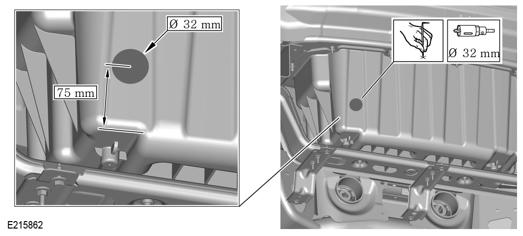
Cut a hole for the towbar wiring harness grommet, as illustrated.

  1. Measure and mark the center point for the hole on the air suspension compressor tray, as illustrated.
  2. Drill a pilot hole using a 2 mm diameter drill bit.
  3. Using a suitable hole cutter, cut a 32 mm diameter hole in the air suspension compressor tray.
27
WARNING
  • This step requires the assistance of another person.
NOTE
  • Use the 6 M12 bolts previously removed from the rear armature of the vehicle.

Install the detachable towbar (A) to the vehicle.

  1. Install the 6 M12 bolts and the 6 washers (G). Bolts should be hand tight only at this stage. There are 3 bolts on each side of the detachable towbar.
28

Replace the towbar wiring harness clip bolts with the longer bolts (C).

  1. Remove the 2 bolts from the vehicle as illustrated.
  2. Install the 2 bolts (C).
  3. Torque 10 Nm +/-1.5 Nm
29

Install the towbar wiring harness socket to the detachable towbar bracket.

  1. Install the fixings (D) and (F).
  2. Torque 12 Nm +/- 1.8 Nm
  3. Press the towbar wiring harness clip into the hole on the detachable towbar bracket.
30

Make sure the towbar wiring harness socket is placed in the stowage position as illustrated.

31
NOTE
  • Make sure the towbar wiring harness grommet fully seals around the hole.

Install the towbar wiring harness grommet to the air suspension compressor tray.

  1. Guide the towbar wiring harness (B) through the hole in the air suspension compressor tray.
32
CAUTION
  • Take care not to damage the loadspace left trim panel.

Remove the blanking plug from the vehicles body harness connector.

  1. Carefully move aside the rear lower edge of the loadspace left trim panel.
  2. Release the clip and remove the blanking plug from the connector.
33

Connect the towbar wiring harness (B) to the vehicle body wiring harness as illustrated.

34

Secure the towbar wiring harness (B) to the vehicle body wiring harness using the tie clips (H) at the 3 locations as illustrated.

35

Secure the towbar wiring harness stud clips as illustrated.

36
WARNING
  • Observe the bolt tightening sequence on both sides of the vehicle.
  • Torque 100 Nm +/-15 Nm

Tighten the detachable towbar bolts in the sequence shown.

  • Torque 100 Nm +/-15 Nm
37
WARNING
  • This step requires the assistance of another person.
NOTE
  • Do not install the rear bumper lower valance (J) at this stage.

Install the rear bumper.

For additional information, please refer to the official Workshop Manual. Rear Bumper (501-19)

38

Install the fixings and washers (D) and (E) through the rear bumper into the towbar support brackets.

  • Torque 5 Nm +/- 1 Nm
39

Install the clip (I) to the rear bumper as illustrated.

40
CAUTION
  • Make sure all the clips are located correctly.

Install the rear bumper lower valance (J) to the rear bumper.

  1. Align and secure the 10 clips..
  2. Install the 6 bolts.
41

Install the tow eye cover (K) to the rear bumper lower valance.

  1. Install the fastener (L) to the tow eye cover panel.
  2. Install the fastener retaining washer (M) to the fastener (L).
  3. Install the tow eye cover panel (K) to the rear bumper lower valance as illustrated.
  4. Hinge the tow eye cover panel upwards and secure by turning the fastener (L) a quarter of a turn using the coin shape provided on the key ring. The fastener (L) locates in the clip (I).
42

Secure the loadspace left trim panel.

  • Install the rear left side D-loop anchor point and fixing bolt.
  • Torque 24Nm
  • Install the 3 clips.
43

Install the loadspace treadplate.

For additional information, please refer to the official Workshop Manual. Loadspace Treadplate (501-05)

44

Install the loadspace cover into the vehicle if required.

45
NOTE
  • A pair of gloves have been provided in the kit (P) for use by the customer when installing and removing the towbar arm.

Remove the dirt cap (N) before installing the towbar arm.

46
NOTE
  • Store the towbar arm installation guide in the vehicle glovebox.

For installation of the towbar arm (P) refer to the separate guide supplied with the towbar arm accessory kit.

  1. Store the towbar arm in the bag when the towbar arm is not in use.
47

Install the dirt cap (N) to the detachable towbar when the towbar arm has been removed.

48

Do not use the Jaguar Land Rover Approved Diagnostic Equipment to configure the detachable towbar electrics.